HOW TO
SCRATCHBUILD A BRIDGE PART TWO
EXPERT MODELLERS SHOW YOU HOW
George Dent describes how he spanned a gap in his backscene by building a low-relief bridge.
PHOTOGRAPHY: GEORGE DENT
As described in last month’s Workbench pages, my ‘Lisburn Lane’ layout project features a baseboard with a ‘dropped’ section, which was originally earmarked to form a river or stream.
The Tim Horn laser-cut plywood baseboard kit is designed to allow the trains to traverse a sunken area of landscape, without the need to raise the track bed significantly (or at all). This is a real bonus for an otherwise flat-topped board, as adding such features usually require the use of an open-framed baseboard.
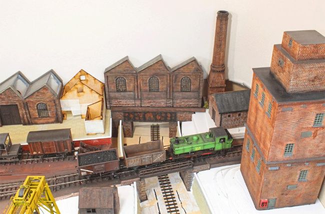
My early plans for a water-based feature changed, and the sunken area will now play host to what will be a moribund colliery or industrial railway line. A length of ‘OO9’ track has been temporarily laid, but a more recent idea is to lay standard gauge ‘OO’ track and employ industrial locomotives with cut-down cabs on the line. The line won’t be powered, so it’s just somewhere to pose stock!
But the decision on track gauge can wait. First, I needed to complete the third crossing of this not-so-great divide, with a bridge that will support part of the factory complex which lines the layout’s backscene.
The previous two bridges feature contrasting styles. The railway is carried on a simple steel decked girder bridge (Wills kit ref. SS49), although I’ve yet to fit the actual decking. This structure was chosen as the side railings wouldn’t obscure the view of the trains as they pass over the bridge. In the foreground is a plate girder road bridge, the construction and weathering of which was explained in last month’s article.