Making sense of the situation, Les Pounder shows us how to use sensors with a robot to get about town!
Making sense of the situation, Les Pounder shows us how to use sensors with a robot to get about town!
OUR EXPERT
Les Pounder is associate editor at Tom’s Hardware and a freelance maker. He blogs about hacks and makes at http://bigl.es.
Our robot can see, well, sort of. It uses pulses of sound to detect objects. But we can also use infrared or a good ol’ button to detect an obstacle.
YOU NEED
The robot build from part two
HC-SR04 P or HC-SR04 and ultrasonic sensor
Obstacle/ PIR sensor Arcade button A strip of M-to-F jumper wires
A breadboard
Code: https://github. com/lesp/ Linux-Format-Robot/ archive/refs/ heads/main. zip
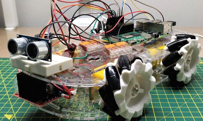
At the end of part two, we had successfully built our robot from a kit, soldered the motors and tested them using a series of directional commands. To facilitate this, we created our own Python module to make things easier to control and abstract away some of the complexities. In this part, we move on to writing code that takes data from sensors and uses it to give our robot ‘brains’.
Sensors, much like our own, provide a means to see and interact with the world around us. We use our eyes to see the world. Robots can see the world around them with OpenCV (Open Computer Vision), which uses machine learning to identify objects and people, and react accordingly. At a more basic level, robots can ‘see’ using ultrasonic and obstacle sensors. There are so many sensors to choose from it can bewilder even the most seasoned of makers. We’ve chosen to stick with the most basic forms: infrared, buttons and ultrasonic sensors. The more advanced methods of input and control will come in a future part.
This part can become quite complex – remember, we are working with multiple types of sensors. We will write the code and test each one as we go. We may use them all, or just a few. That is a decision for you. Make your robot as complex or simple as you wish – we will give you the tools and the knowledge to realise it. Start with a single sensor, learn how it works and then apply that knowledge to your build. The online resources have all of the code snippets for you to add to your code, and our robot.py file contains every function for every sensor we create in this tutorial.
Additional features
In part two, we created a series of motor tests (forward, backward, spins, stops) but we left one out. This isn’t so much a test, rather a routine that our robot can follow when it encounters an immovable object. The routine is called make_space and its goal is to back the robot away from an object, spin and then try again. It is a function that calls the other motor functions.
Open the robot.py module in your favourite editor and add these steps.
Part Three! Don’t miss next issue, subscribe on page 16!
Once these steps are complete, the robot can continue on. If there is another obstacle, the routine can be called again. Save the function to robot.py. Later, we will use this function as a means of helping our robot escape a situation.
Plenty to sense
The world of electronics has a dizzying array of sensors. We can measure acceleration forces, magnetic fields and orientation. But the best sensors from gpiozero import PWMOutputDevice, Button
Scroll down the code to the end – our last function was stop(). After this function, create a new function called impact: for a robot are those that give it the ability to sense the world around it. We can start basic with a bump sensor, essentially a button, then work our way to distance sensors, which use pulses of sound to measure our distance from an object. Remember that we don’t need to use every sensor on our robot; choose the sensor(s) that will complement your build. At the end of this part, we will have updated our Python module to feature new functions for working with each sensor.
Bump it!
Bump sensors are the most basic of robot sensors. Really, they aren’t a sensor in the truest form. Rather they are simply buttons that when pressed trigger an action to happen. Just like the buttons on a game controller. Our bump sensor can be an arcade button glued to the front of the robot chassis. As the robot touches an object, the button is pressed and the state of a GPIO pin is changed. In our case, the GPIO pin is pulled high when the button is not pressed. Pressing the button connects the button to GND, causing the GPIO pin to go low and triggering a function that stops the motors, then reverses.
The circuit for the bump sensor is a simple two-wire connection. One leg of the button connects to GPIO2, the other to GND. It doesn’t matter which leg. We used a large arcade-style button for this as it is designed to take high impacts and we can easily attach it to the front of the robot. The button needs to be proud (stuck out) from the front of the chassis so the button hits the object before the robot.
Going to the code and inside the Python module, robot.py, that we created in part two, we now need to add a few more lines of code. We edit the first line, which imports classes from the GPIO Zero module. We already have PWMOutputDevice that we use to control the motors, now we add Button to the line.
Obstacle sensors are really PIR sensors that have a narrow and short field of vision. We can use them to detect walls, people, pets and so on, and have the robot react accordingly.
By creating a module full of functions, we have created our own, highlevel interface for controlling the robot. There is no right or wrong way to control it; use the functions to create your own sequence of commands.
SENSOR KITS
You can spend lots of money on sensors and, over the years, we have done just that. If you are starting out, it is best to pick up a kit of different sensors. These kits can be found on Amazon for £20-£50 and come with a plethora of components, including many that can be used in non-robotics projects. Tilt switches, photo-interrupter, avoidance, flame and lasers can all be yours, thanks to these handy kits. Our advice is to pick one up and use it to experiment with the sensors and your Pi. But we also suggest you pick up an HC-SR04P (or +) instead of the bundled HC-SR04. The HC-SR04 requires a potential/voltage divider, consisting of two resistors, which drops the output (echo) pin’s voltage down from a damaging 5V to 3V. Never use an HC-SR04 on a Pi or Pico without a voltage divider or a logic level converter. Save the hassle and get the P/+ variant instead.
If you fancy something more sophisticated, a time-of-flight array is great for measuring distances with more accuracy. The VL53L5Cx has an 8 x8 array that uses lasers to measure distances between 2cm and 4m. This tiny sensor can return values and basic shapes instead of distances, giving your robot a greater understanding of the world around it. It can be found for around £20 at Pimoroni.
Ultrasonic sensors are the easiest and best way to give your robot sight. The new P and + models work out of the box with the Raspberry Pi and Pico.
QUIK TIP
For Raspberry Pi and Pico-based robotics, look for HC-SR04P and HC-SR04+ ultrasonic sensors. They work out of the box with the Raspberry Pi and can be used with 3V logic (Micro:bit, Adafruit, ESP8266 and so on) and 5V logic (Arduino) boards.
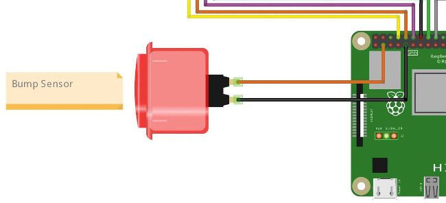
Our bump sensor is really an arcade button, designed to take high impacts. When the button is pressed, it completes a circuit and changes the state of a GPIO pin, causing an action to happen.
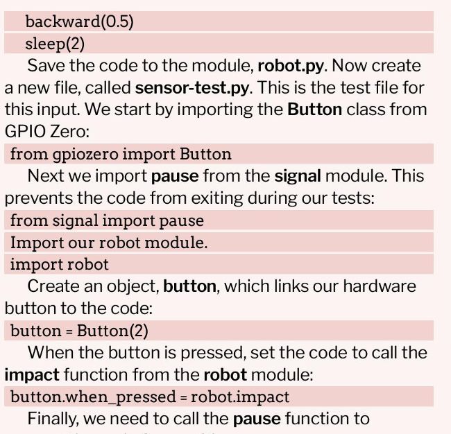
pause()
Save and run the code. Quickly press the button to trigger the impact function to run. We’ve just created our first, basic sensor for the robot.
Passive infrared
Passive infrared (PIR) sensors are a common sensor in maker electronics. The sensors, typically BISS0001, are simple to use and relatively reliable. They are used to detect movement using infrared. Everything emits a low level of IR radiation, and this sensor is designed to detect changes, such as a person or animal moving into its field of view. When triggered, the output pin moves from high to low, giving us an event that we can use to trigger an action. Standard golf ball-shaped sensors are better used for alarm projects, but PIR obstacle sensors can be used as a crude means to detect objects and people.
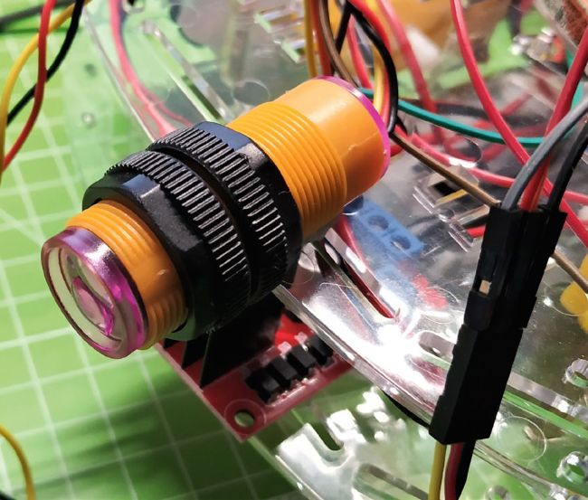
We used an obstacle sensor specially made for robotics. It uses the same basic premise as a typical PIR sensor, but has a shorter and narrower field of vision. The detection distance can be tuned using a potentiometer (a screw) on the back of the sensor.
The sensor (see top-right) has three pins: power (VCC), out and GND. Typically these are identified by their colours (red, yellow and black, respectively). The red wire connects to 3.3V on the Pi, black to any GND pin, and yellow, the out pin, connects to GPIO4. See the diagram Obstacle.png in the project downloads.
With the sensor connected, we need to add a few lines of code in order to make it work. This code is added to our robot.py module, which contains all the commands to make our robot work. Firstly, we need to update the GPIOZero import so that it now includes the MotionSensor class: from gpiozero import PWMOutputDevice, Button, MotionSensor
Underneath where we configured our motors (rra, rrb and so on), we need to create a new object, obs (short for obstacle), which uses the MotionSensor class to configure the sensor on GPIO4: obs = MotionSensor(4)
Scroll to the bottom of the file, past the impact function, and create a new function called obstacle: def obstacle():
Inside the function, we use print to write a message to the Python shell, informing the user that the sensor is searching for an object. print(“Checking for object”) When it ‘sees’ an object, it triggers the sensor to change state, and in this case it runs the stop() function to immediately stop the robot. We use when.motion because the obstacle sensor and a standard PIR sensor work in the same manner. obs.when_motion = stop Save the code and open sensor-test.py. Clear any existing code as we are going to create a new test just for the obstacle sensor. Import the robot module: import robot robot.obstacle()
Save the file and click Run to start the test script. The function runs and prints Checking for object . Place your hand in front of the sensor. The LED in the sensor lights up, the Python shell prints STOP! and the stop function halts the motors. We have successfully tested our obstacle sensor.
Ultrasonic the robot
You’re reversing the car and hear a “beep, beep, beep”. As you get nearer to the garage door, you hear “BEEP!” That is a distance sensor. It sends a ping of ultrasound at 3,440cm/s, and waits for the returning echo. The time taken for the ping to send and receive is halved, then multiplied by the speed of sound to give distance.
The common distance sensor for Arduinos and Raspberry Pi is the HC-SR04. We’re using the HC-SR04P (or you can use the + model) as it is compatible with the 3V logic used by the Pi’s GPIO. The older HC-SR04 uses 5V logic, and requires a potential divider to drop the echo pin’s output from 5V to 3V. In the past, we have handcoded our own function to calculate and return the distance, but luckily GPIO Zero has a built-in function, DistanceSensor, that removes the maths from our code. That said, learning how to write your own function to handle this is a basic skill for most robot makers.
Call the obstacle function:
Going to our code and inside the Python module, robot.py, that we created in part two, we need to add a few more lines of code. We edit the first line that imports classes from the GPIO Zero module. We already have PWMOutputDevice that we use to control the motors, and now we add DistanceSensor : from gpiozero import PWMOutputDevice, DistanceSensor
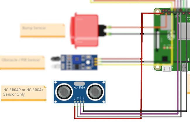
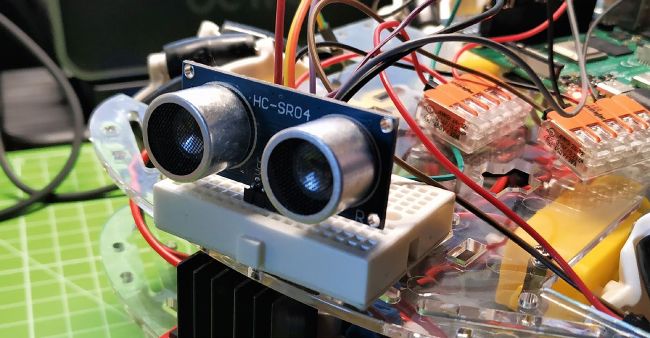
Ultrasonic sensors have four pins: VCC for power, GND and a trigger pin to send a pulse of sound, plus an echo pin to listen for the returning pulse.
Next add an object, sensor, underneath where we defined the motors (rra, rrb, and so on). This specifies the GPIO pins used for the sensor, in this case GPIO27 and 17. Pin 27 is our echo pin, 17 the trigger: sensor = DistanceSensor(27, 17)
Now we go right to the bottom of the code and create a function, ultra (short for ultrasonic): def ultra():
The function first creates an object, distance, and in there it stores the distance measured. Note that the function returns the value in metres, so we multiply the values by 100 for centimetres. We use round to round the measurement to two decimal places. distance = round(sensor.distance*100,2) Print the distance as part of a sentence to the
Python shell: print(‘Distance to nearest object is’, distance, ‘cm’) Use a conditional test to check the distance. If it is below 50cm, call the make_space function that we created earlier:
Rise of the robots!
We’ve tinkered with the sensors and now it is time to put our tinkering to the test with a basic script that uses the ultrasonic sensor to measure the distance of objects ahead of our robot. If an object is less than 50cm away, the robot stops, spins and backs away before trying again. Tweak the detection distance via the ultra function in robot.py. We chose 50cm as a conservative estimate so it triggered the make_space function; 10-20cm would be better in the home.
Create a new file called autonomous_test.py and import the robot module: import robot
Use a try exception handler to run the main body of code. If this fails, an exception prevents the robot from running away: try:
while True:
Call robot.ultra to run the ultrasonic sensor, check the distance and use the conditional logic inside the function to decide whether to move forward or escape:
Use a forever, while True loop to run the code:
if distance < 50: make_space() robot.ultra()
Here is where the exception handling kicks in. Should the worst happen, we can press Ctrl+C to stop the code, print a message, stop the motors and exit: except KeyboardInterrupt: print(“STOP”) robot.stop() Save the code and click Run to test it. Lift the robot off your desk, otherwise you will be chasing it around the room. Press Ctrl+C to stop the code and robot.
Where are we?
We now have a series of sensors that we can use with our robot. Our choice was the ultrasonic distance sensor, chiefly because this sensor is so easy to use and provides our robot with great long-distance sensing and obstacle avoidance. Tinker with the code, and make it your own. Remember, this is your robot.
The obstacle sensor has three pins: VCC for power, GND and a data/output pin, which changes state when it detects a person or object.
MOUNTING SENSORS TO A ROBOT
Placing sensors on your robot can be tricky. Ultrasonic sensors need to face forwards, bump sensors can be placed around the chassis, line followers need to go under the chassis. But how do we connect them all to the chassis? Your approach depends on what resources you have. We can glue sensors to the chassis, using cable ties to provide strain relief to the jumper wires. Gluing Lego bricks to the chassis and using them tomake a frame is one way to secure your sensors. We can fabricate our own frames using balsa wood, or laser cut our own frames if we have access to a makerspace. The best approach is to 3D print holders or frames for our sensors, and the best thing is, many people have done so and shared their models online. Libraries such as http://printables.com and http://thingiverse.com have an overwhelming number of 3D printable holders for our sensors, many of which don’t take much time to print. Sure, you need a 3D printer, but they’re coming down in price. Creality’s Ender 2 Pro is a solid performer for around £150. We know, because we own one. Downloaded parts can be tweaked to suit your needs. Tinkercad is an excellent online resource to tweak 3D models. We can also use Blender, OpenSCAD and FreeCAD to edit and make our own parts.