GPRTK.GPIO
Add Raspberry Pi GPIO to your PC
PCs don’t offer a GPIO header like the Raspberry Pi, but Mike Bedford reveals that a low-cost add-on is all you need to join in the fun.
Credit: https://github.com/PiSupply/Ryanteck
OUR EXPERT
Mike Bedford uses both PCs and Raspberry Pis, so is quite taken with this method of providing convergence between the two platforms.
The Raspberry Pi might be the poor relation to the PC in performance, but that diminutive single-board computer wins hands down in one area. While a PC’s interfacing options are limited to USB, video, audio and wired and/or wireless networking, the Pi adds the all-important GPIO. That, in turn, enables it to be used to control and monitor external electronics and sensors, and thereby work in conjunction with pretty much any equipment.
Thanks to the Ryanteck RTk.GPIO board, all that changes, and an ordinary PC can, like the Pi, be used with external electronics and hardware. Here we’re going to see how to use the RTk.GPIO, irrespective of whether or not you’re a Raspberry Pi user. If you’re a Pi user, this board enables you to migrate some of your projects to your PC, or use some of your Pi HATs – the add-on boards that plug into the Pi’s GPIO connector – with a PC. Alternatively, if you’re firmly in the PC-only camp, the RTk.GPIO gives you the opportunity to get some experience of real-world interfacing.
Add-on hardware
While PCs don’t have a general purpose input/output (GPIO) port as standard, various hardware solutions are available to add this missing functionality. Traditional products that do this are generally referred to as data acquisition, or DAQ, devices, and connect via USB or occasionally plug into the motherboard. They usually provide digital and analogue I/O so, in that respect, are more powerful than the Pi’s GPIO. However, they don’t offer any level of compatibility with the Pi GPIO, so migrating projects or HATs isn’t easy. However, the biggest drawback is cost. Products start upwards of £100 and rise to several thousands.
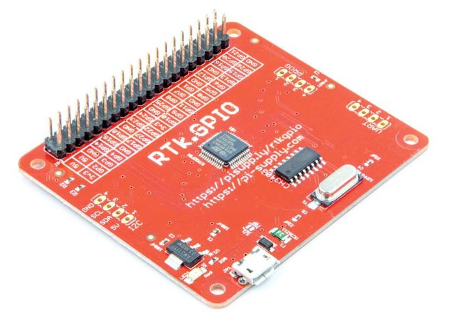
The RTk.GPIO costs just a few pounds and adds a GPIO port, similar in most respects to the Pi’s, to your PC.
CREDIT: ELEGOO
QUICK TIP
We didn’t have a sufficiently demanding application to put it to the test, but we did note some online postings about the RTk.GPIO that compared its response time unfavourably to that of the Pi. However, we suspect it won’t be an issue for most users’ applications.
PWM BASICS
The Raspberry Pi’s GPIO header is entirely digital, so there are no analogue outputs or inputs. However, using PWM – which the Pi supports, but the RTk.GPIO can only provide via software – it’s possible to generate an analogue output signal on a GPIO output pin, albeit with limitations. Given that not all Pi users will be familiar with PWM, here’s a brief intro.
PWM stands for pulse width modulation, and the diagram (right) shows how it works. In the top part, the output pin is shown as set to a binary 0, so the pulse width is 0% and the voltage is 3.3V. In the middle part, the PWM has a 50% pulse width, so the average output voltage is half of 3.3V, namely 1.65V. The other parts show 25%, 75% and 100% widths. If the frequency of the pulses is high enough, and the requirement isn’t too demanding, this works as well as outputting a true analogue voltage. If you use it to drive an LED, for example, and the frequency is at least 100Hz, we wouldn’t see it flickering on and off, so it could be used for dimming the LED.
Better approximation to a steady analogue voltage can be achieved using an RC (resistorcapacitor) circuit to average out the pulses and give something more like the dotted red lines. This reduces the speed at which the analogue voltage can change, although using a higher PWM frequency, and thus a lower value of capacitor, helps. This means the RTk.PIO’s slower software-based PWM isn’t as good as the Pi’s hardware PWM.