TUTORIALS Guide to breadboards
Getting to grips with breadboards
MAKER BASICS
Mike Bedford provides a hands-on guide to using breadboards for those starting out with the Raspberry Pi or other single-board computer projects.
OUR EXPERT
Mike Bedford used to be more comfortable dealing with software than hardware, but his familiarity with the latter shows that you don’t have to stick with just the one area of expertise.
QUICK TIP
Some components have stranded wire leads because these are flexible, but they don’t easily plug into a breadboard. Sometimes the manufacturer tins the end of the leads with solder. If not, the easiest solution is to extend each of the device’s leads with a proper patch lead, using a small piece of terminal strip.
One of the best things about Raspberry Pi or Arduino single-board computers (SBC), or similar, is that they provide a GPIO (general purpose input/output) facility that enables them to be connected to external devices. This offers the opportunity to learn about embedded computing and, once you’re up to speed, use your SBC in so many exciting projects. Usually, though, you can’t attach those external devices to pins on the GPIO. Instead, it’ll be necessary to use some simple interfacing circuitry.
Without some experience of electronics this might sound daunting for a couple of reasons. First, it won’t be immediately obvious what arrangement of components is needed. Even if you’re presented with a circuit diagram, it might not be easy to convert that schematic into a real-world assembly of components that you can attach to your single board computer. It’s that second issue that we address here by providing an introductory guide to building circuits on so-called breadboards. Why the word breadboard? It’s because at one time electronics engineers used real wooden boards (even using actual dime-store breadboards) for prototyping circuits, using wood screws as binding posts.
Breadboard benefits
The traditional way of building electronic circuits involves soldering them together. That’s exactly how the motherboard in your PC will have been manufactured, but it’s built on a PCB (printed circuit board) which you’re not going to want to design until you’re certain that your circuit works as intended. An option that’s more suitable during the prototyping and testing phase is to use a stripboard, but it still involves soldering, for which you’d need a soldering iron and a few other hand tools. That means that making alterations to the circuit isn’t easy and the components can’t really be re-used.
As an alternative to soldering, a circuit could be assembled using a piece of terminal strip, but although this enables changes to be made simply and components could be re-used, it’s really only suitable for trivially simple circuits.
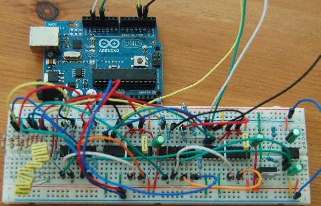
You’re not going to be building a complex circuit like this anytime soon, but this example shows the potential of breadboards for prototyping.
George P. Macklin,
CC BY-SA 2.0, www. flickr.com/photos/gmacklin/5079459828/
A breadboard provides a win-win solution for testing out circuits. Depending on its size, it even enables fairly complicated circuits to be built, and because it doesn’t involve soldering, changes can easily be made. It’s even possible to reuse the components, although you need to recognise these are just for early prototyping and are unsuitable for field work.